Home / News / Industry News / What Makes Mechanical Sheet Metal Processing Essential for Precision Engineering
Industry News
Home / News / Industry News / What Makes Mechanical Sheet Metal Processing Essential for Precision Engineering
What Makes Mechanical Sheet Metal Processing Essential for Precision Engineering
Understanding Mechanical Sheet Metal Processing
The term "mechanical" in mechanical sheet metal processing refers to fabrication methods that meet rigorous engineering standards for industrial applications. Unlike basic metal bending, mechanical sheet metal work demands precise tolerances, structural integrity, and assembly compatibility. This distinction matters because mechanical applications—from automotive components to industrial machinery—cannot tolerate deviation.
When you specify mechanical-grade fabrication, you are requesting more than cutting and bending. You are demanding repeatability, material traceability, and dimensional accuracy that enables parts to function within complex systems. The difference between commercial and mechanical tolerances can determine whether your assembly succeeds or requires costly rework.
Core Capabilities in Mechanical Sheet Metal Fabrication
Professional mechanical sheet metal services integrate multiple precision processes into a coordinated workflow. Each capability builds on the previous one, creating a complete solution path from design to finished assembly.
Laser Cutting and CNC Punching
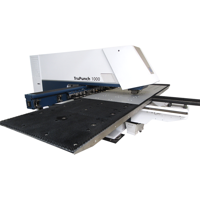
Laser cutting achieves precision up to 0.1mm on carbon steel, stainless steel, and aluminum materials ranging from 0.5mm to 6mm thickness. This technology produces clean edges with minimal thermal distortion, eliminating the need for secondary edge finishing in most applications. CNC punching handles high-volume perforations with consistent hole placement, crucial for ventilation panels, control board mounting, and cable management enclosures.
Precision Bending and Forming
Multi-axis CNC bending machines control springback compensation and achieve bend angle tolerances of plus-minus 0.5 degrees under standard conditions, tightening to plus-minus 0.1 degrees for critical applications. Advanced tooling prevents radius distortion and maintains consistent inner bend radii across production runs. Complex geometries with compound bends are performed with fixture support to ensure part-to-part consistency.
Welding and Assembly Operations
MIG, TIG, and spot welding combine components using custom jigs that position parts within tolerance specifications before joining. Welding parameters are documented and validated through first-article inspection. Structural integrity is verified through non-destructive testing when required by application demands.
Surface Finishing and Protection
Powder coating, electroplating, anodizing, and zinc plating protect metal surfaces while meeting performance requirements. Material selection and surface treatment are coordinated—galvanized steel for outdoor industrial equipment, anodized aluminum for food processing machinery, stainless steel passivation for pharmaceutical environments.
Materials for Mechanical Applications
Material selection directly impacts mechanical performance, cost, and production speed. The following materials are standard for mechanical sheet metal work:
Material Grade
Primary Applications
Key Advantages
Carbon Steel, Galvanized
Industrial frames, outdoor enclosures
Cost-effective, corrosion resistance when galvanized
Mechanical applications demand measurable quality standards. Vague specifications lead to part failures and assembly problems. Clear tolerance documentation prevents rework and ensures first-time fit.
Standard Versus Tight Tolerance Performance
Standard mechanical tolerances operate at plus-minus 0.5mm on linear dimensions and plus-minus 0.5 degrees on bend angles. Tight tolerances achieve plus-minus 0.1mm linear accuracy and plus-minus 0.1 degrees on angles, requiring additional setup time, inspection cycles, and material waste factors. Understanding which features need tight tolerances—and which can accept standard—optimizes cost and lead time.
Quality Control and Certification
First article inspection validates that tooling and setup produce compliant parts before full production begins. Dimensional records are maintained with measurement data, tooling photos, and material certifications. For applications requiring traceability, mill certificates document material composition and heat treatment history.
From Design to Production: The Complete Process
Understanding the mechanical sheet metal production workflow reduces uncertainty and accelerates your project timeline.
Design for Manufacture (DFM) Feedback
Submitting CAD files triggers a comprehensive design review that identifies potential manufacturing challenges before production begins. DFM analysis addresses bend sequence, draft angles, radius minimums, hole placement, and welding feasibility. This step prevents costly design changes later and often reduces part cost through manufacturing-friendly suggestions.
Prototyping Versus Production Volume
Prototyping runs (1-10 units) verify form, fit, and function with minimal tooling investment. Setup costs are absorbed over fewer pieces, resulting in higher per-unit cost but faster delivery. Production runs (100+ units) justify custom tooling that reduces per-piece cost while maintaining consistent quality. Many projects begin with prototypes to validate design before committing to tooling for volume production.
Key Industries Served by Mechanical Sheet Metal Parts
Different industries demand specific capabilities. Recognizing your application ensures the supplier understands your performance requirements without extensive explanation.
Industrial Machinery Frames and Enclosures
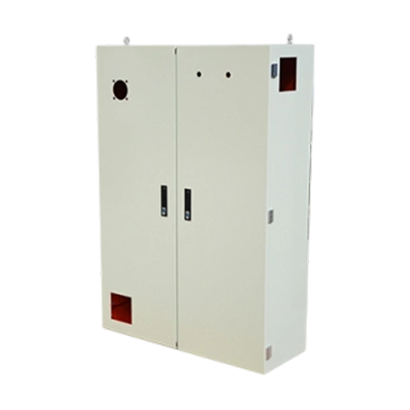
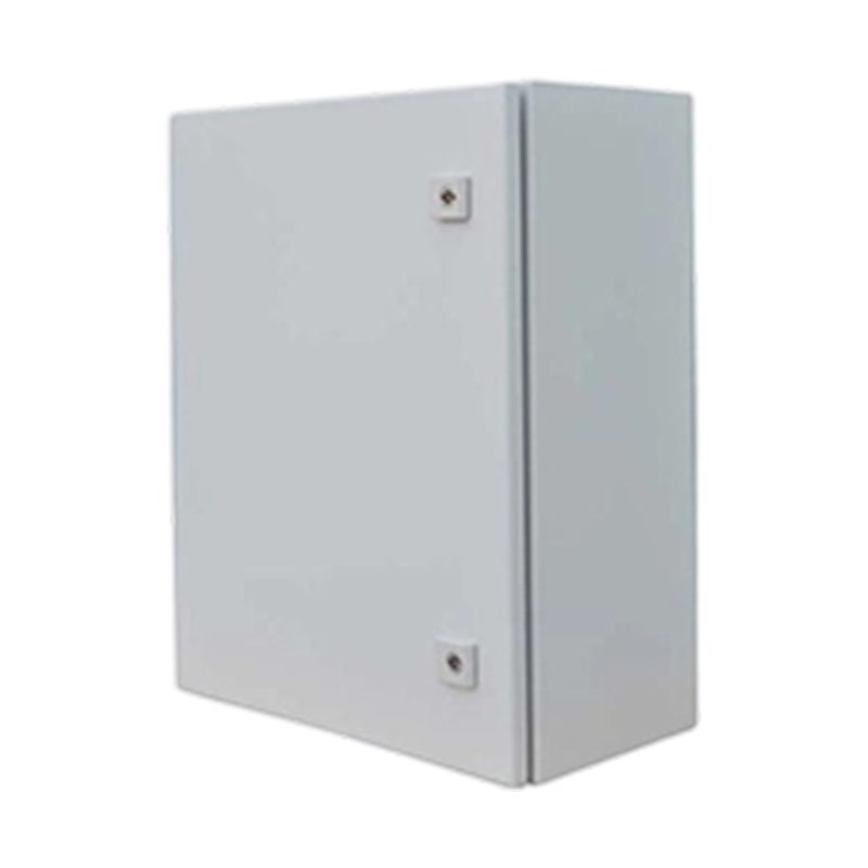
Manufacturing equipment, assembly machines, and control cabinets require structural rigidity and dimensional stability under load. Welded frames distribute stress uniformly, powder-coated exteriors protect against workshop environments, and internal brackets position components with precision. Enclosure design balances access for maintenance with protection of sensitive electronics.
Automotive and Electric Vehicle Components
Vehicle structural components and battery enclosures demand high-strength materials, consistent dimensional tolerance, and repeatable welding quality. Production volumes justify advanced tooling, and safety specifications require documented quality procedures. Material certifications and traceability are non-negotiable in automotive supply chains.
Electronic Control Cabinets and Chassis
Control cabinets house automation equipment, power distribution, and communication devices. Internal geometry must accommodate circuit boards, cable trays, and cooling systems. External dimensions often comply with industry standards for mounting and stacking. Finishing protects components from humidity, dust, and temperature fluctuations.
Requesting a Quote for Your Mechanical Sheet Metal Project
Accelerate the quoting process by providing complete information upfront. Incomplete submissions delay feedback and create uncertainty about project feasibility.
Required Information for Accurate Quotes
3D CAD file (STEP format preferred, IGES or native CAD formats accepted)
2D engineering drawing with tolerances, bend angles, and hole locations
Quantity required and desired delivery timeline
Material specification (carbon steel, stainless steel, aluminum grade)
Assembly or weld specifications if components combine
Submitting organized documentation reduces quote turnaround from days to hours and provides more competitive pricing because the supplier understands your requirements precisely.
Why Precision Tolerances Matter in Mechanical Assembly
Tolerance is not an abstract specification—it is a practical constraint that determines whether components fit together and function as designed. Accumulation of tolerance errors across multiple parts can prevent assembly entirely.
Consider a simple example: an enclosure frame assembled from four welded sides and a bottom panel. If each component accumulates a tolerance error of 0.2mm in one direction, the combined error reaches 1mm, potentially preventing the panel from seating. Mechanical-grade processing controls this error through:
Tooling precision that repeats each bend and cut within specification
Fixture design that controls assembly geometry during welding
Documented inspection that confirms compliance before shipment
A supplier who dismisses tolerance concerns as over-specification will ultimately cost you far more in assembly delays and rework than the premium for consistent quality.
Cost Optimization Strategies for Mechanical Fabrication
Mechanical quality does not require unlimited budget. Smart design choices reduce cost while maintaining performance.
Material Selection and Volume Considerations
Stainless steel costs 2-3 times more than carbon steel, but justifies the expense in corrosive environments. For non-corrosive applications, galvanized carbon steel delivers durability at lower cost. Volume influences material availability—specialty grades may require longer lead times for small quantities.
Standardizing Design Features
Custom bend radii, unusual hole sizes, and non-standard dimensions increase tooling complexity. Standardizing features on common bend radii and hole sizes reduces setup time and enables shared tooling across similar projects. Designers who understand manufacturing constraints create designs that are both high-performance and cost-effective.
Phased Production Approach
Prototyping validates design before full tooling investment. Initial prototype costs are higher per unit, but provide critical data for refining the design before committing to volume tooling. This approach reduces the risk of expensive mistakes and accelerates time-to-market.
Common Challenges in Mechanical Sheet Metal Processing
Understanding typical obstacles helps you anticipate solutions and communicate more effectively with your supplier.
Springback in Precision Bending
Material properties cause bent components to partially straighten after the tooling releases. The effect increases with material strength and thickness. Controlling springback requires experience with specific alloys and precise tool angles. High-tolerance bends demand compensation calculations and adjustment through repeated bending trials during setup.
Weld Quality and Distortion
Heat from welding causes adjacent material to expand and contract, creating distortion. Controlling weld sequence and cooling rates minimizes warping. Tack welds secure components before full welding begins. Fixturing prevents movement during cooling. Suppliers experienced in mechanical welding employ these techniques as standard practice.
Surface Finish Integration
Coating and plating processes require clean surfaces free from oils, oxides, and welding residue. Improper surface preparation undermines finish quality and durability. Mechanical processing that maintains cleanliness throughout production simplifies finishing and improves final results.
Frequently Asked Questions About Mechanical Sheet Metal Processing
Send your 3D CAD file (STEP format) along with a 2D drawing showing tolerances, bend angles, and assembly requirements. Include material specification, finish requirements, quantity needed, and desired delivery date. Professional suppliers respond with a detailed quote and DFM feedback within 24-48 hours. Free design analysis is standard for serious projects.
Q2: What is the typical lead time for custom sheet metal parts?
Prototypes typically ship in 5-10 business days after quote approval, depending on complexity and current shop capacity. Production runs require 2-4 weeks for tooling and setup, then additional 2-3 weeks for manufacturing, inspection, and finishing. Expedited schedules are possible at premium cost if capacity allows.
Q3: Can you handle both prototyping and mass production within the same project?
Yes. Many projects begin with prototype validation using soft tooling, followed by production runs using hardened tooling. This phased approach reduces risk and initial investment. Prototype and production parts maintain design compatibility, ensuring designs validated in prototyping scale directly to volume production.
Q4: How do you ensure structural integrity of welded assemblies?
Welded joints are designed using structural analysis to distribute loads appropriately. Welding procedures are qualified through testing and documented for repeatability. First-article inspection includes visual examination, dimensional verification, and sometimes destructive or non-destructive testing depending on application criticality. Material certifications trace composition and heat treatment history.
Q5: What tolerances can you achieve on bent angles?
Standard bend tolerances are plus-minus 0.5 degrees. Tight tolerances of plus-minus 0.1 degrees are achievable with advanced CNC bending, precision tooling, and material compensation. Specification depends on the application—cosmetic angles may accept standard tolerances, while functional angles (interference fits or alignment features) require tighter control.
Q6: How do material thickness and strength affect pricing?
Thicker material requires more powerful punching and bending equipment, increasing labor time and tooling wear. High-strength materials demand slower processing speeds and specialized tooling. Both factors increase cost per unit. Material selection should balance performance requirements with cost constraints, and your supplier should explain cost drivers transparently.
Q7: What information should be included in my engineering drawing?
Include overall dimensions with tolerances, bend angles and bend radii, hole locations and sizes, material thickness, material grade, surface finish, and any assembly or weld notes. Clearly identify which features require tight tolerances and why. Notes explaining functional requirements help the supplier optimize manufacturing approach.
Q8: Can powder coating be applied to aluminum parts?
Yes. Aluminum requires surface preparation including cleaning and a conversion coating (chromate-free options are standard). Powder coating then adheres well to properly prepared aluminum. Color options are extensive, and the finish provides excellent durability and UV resistance.


 English
 русский
 Español
 中文简体
中文简体