Home / News / Industry News / What Mechanical Production Equipment Actually Determines Sheet Metal Fabrication Quality
Industry News
Home / News / Industry News / What Mechanical Production Equipment Actually Determines Sheet Metal Fabrication Quality
What Mechanical Production Equipment Actually Determines Sheet Metal Fabrication Quality
What Mechanical Production Equipment Actually Determines Sheet Metal Fabrication Quality
Mechanical production equipment is not a list of machine names. It is a coordinated system of cutting, punching, forming, joining, and inspection assets that together decide whether a sheet metal part meets its drawing tolerance, surface requirement, and delivery schedule. A buyer comparing suppliers often receives a catalogue of lasers, presses, and brakes. That catalogue says little about whether a 3 mm stainless steel bracket will be cut square, whether a 2.5 m enclosure will bend without twist, or whether the ten thousandth part will match the first.
This guide examines the technical logic behind mechanical production equipment in sheet metal fabrication. It focuses on process capability, tolerance chains, tooling strategy, material behaviour, and the commercial questions that determine whether a supplier can actually deliver a custom cabinet, housing, or stamped component. The aim is practical: to give engineers and procurement teams a framework for evaluating equipment beyond the specification sheet.
Our Mechanical Production Equipment Capabilities
A fabrication shop is only as strong as the handoff between its processes. The following matrix describes core equipment groups by the manufacturing result they produce, not by the machine label alone.
High precision laser cutting systems: produce complex contours, tight kerf widths, and burr controlled edges in mild steel, stainless steel, aluminium, brass, and copper.
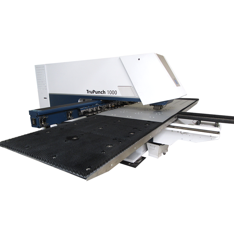
CNC punching machines: execute high volume hole patterns, louvers, countersinks, and formed features with repeatable tool positioning.
CNC press brakes: form bends with controlled angle deviation, back gauge accuracy, and repeatable springback compensation.
Shearing and slitting equipment: prepare flat blanks with straight edges and controlled width tolerance before forming.
Welding and joining systems: combine MIG, TIG, spot, and riveting processes to assemble enclosures without distorting thin gauge panels.
Surface treatment lines: apply powder coating, zinc plating, anodising, and brushing to meet corrosion and appearance specifications.
Coordinate measuring machines and inspection tools: verify hole position, bend angle, flatness, and assembly fit against the original CAD model.
The equipment list matters less than the process window each group can hold. A laser cutter rated for 20 mm mild steel may still produce unacceptable taper on a 12 mm stainless part if the assist gas strategy and focus position are not matched to the material. A press brake with a 3 m bed may still fail on a 2.5 m cabinet side if the tooling crown is not compensated for deflection.
How Tolerance Chains Accumulate Across Mechanical Production Equipment
Every fabrication process introduces deviation. The final part tolerance is the sum of those deviations, not the best single machine in the shop. Understanding the chain is essential when specifying custom control cabinets, equipment housings, or precision stamped parts.
Cutting deviation
Laser cutting typically holds position accuracy within plus or minus 0.05 mm for thin gauge material, but heat affected zone, kerf taper, and dross formation can push effective edge quality outside that band. The deviation propagates into the bend allowance calculation.
Punching deviation
CNC punching repeats tool position within plus or minus 0.1 mm on a well maintained turret. However, tool wear, sheet movement, and clamp repositioning can double that figure across a large panel with many hits.
Forming deviation
Press brake angle deviation depends on material springback, tooling wear, and ram deflection. A typical target is plus or minus 0.5 degrees for general work, tightening to plus or minus 0.25 degrees with angle measurement and compensation.
Assembly deviation
Welding distortion on thin gauge enclosures can exceed the sum of all previous deviations if fixture design and weld sequence are not controlled. Spot welding and riveting reduce heat input but introduce their own positional tolerance.
Material Behaviour and Equipment Selection
Mechanical production equipment for sheet metal fabrication must be matched to the material, not only to the part geometry. The same machine can behave very differently across stainless steel, aluminium, copper, and mild steel.
Material
Typical thickness range
Cutting consideration
Forming consideration
Mild steel
0.5 to 20 mm
Oxygen assist for thick sections
Low springback, predictable bend allowance
Stainless steel
0.5 to 12 mm
Nitrogen assist to avoid oxidation
High springback, work hardening risk
Aluminium
0.5 to 10 mm
High reflectivity demands power control
Soft surface, tool marking risk
Copper and brass
0.5 to 6 mm
High reflectivity, narrow process window
Excellent ductility, but galling possible
Thickness alone does not determine equipment choice. A 6 mm aluminium part may cut faster than a 3 mm stainless part because the laser absorption and thermal conductivity differ. A press brake that forms mild steel without issue may need a different tooling radius and compensation strategy for stainless steel of the same thickness.
Tooling Strategy for Custom Control Cabinets and Equipment Housings
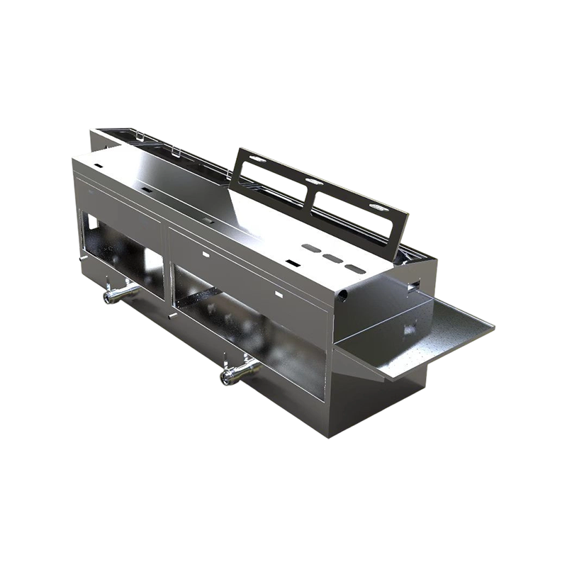
Custom control cabinets and equipment housings are rarely simple. They combine large flat panels, multiple bend lines, cutouts, ventilation features, mounting bosses, and assembly interfaces. The tooling strategy determines whether those features can be produced repeatedly without secondary operations.
Standard punch tooling: covers round holes, slots, and rectangular cutouts. Best for high volume, simple patterns.
Forming tooling: produces louvers, embosses, countersinks, and tabs in the punching stage, reducing press brake operations.
Segmented press brake tooling: allows different bend lengths and radii on the same setup, which is essential for cabinets with mixed bend lines.
Special radius tooling: matches the design intent for cosmetic bends on equipment housings, where a sharp radius would create a visible crease or stress concentration.
Fixture and gauge tooling: holds parts during welding and assembly so that hole patterns and bend angles remain aligned.
Tooling cost is often the deciding factor between a dedicated setup and a flexible one. For a custom control cabinet project with a one time order, the supplier may choose standard tooling and accept a longer setup time. For a repeat production programme, dedicated tooling reduces cycle time and improves repeatability.
How We Work: From Requirement to Delivered Enclosure
The equipment is only part of the system. The workflow around it determines whether the part arrives on time and to specification.
Requirement analysis
The supplier reviews the drawing, material specification, surface finish, and assembly interface. At this stage, the process route is selected and any design for manufacturability issues are raised before tooling is committed.
Design and sample
A sample or first article is produced to validate the tolerance chain. For custom equipment housings, this may include a full assembly check with mating components. The sample is measured and compared to the CAD model.
Production and quality control
Production runs use the validated process route. In process inspection checks critical dimensions at defined intervals. Final inspection verifies the complete part against the drawing and any agreed cosmetic standard.
Global delivery
Packaging is designed to protect painted or brushed surfaces during transport. Documentation includes inspection reports, material certificates, and any required compliance declarations.
Application Cases: Where Equipment Capability Meets Industry Demand
Different industries place different demands on mechanical production equipment. The following examples show how equipment selection changes with the application.
New energy storage cabinets
Energy storage cabinets require large, flat panels with precise cutouts for busbars, ventilation, and cable entry. The tolerance chain must hold across a 2 m tall assembly so that doors align and internal components fit. Laser cutting plus CNC bending with angle compensation is the typical route. Welding distortion is controlled through fixture design and a balanced weld sequence.
Medical equipment housings
Medical housings often use stainless steel or aluminium with brushed or anodised surfaces. Cosmetic requirements are strict, so tooling must avoid marking the visible face. Punching is preferred over laser cutting where edge quality and surface protection are critical. Forming tooling produces clean radii without secondary polishing.
Industrial control cabinets
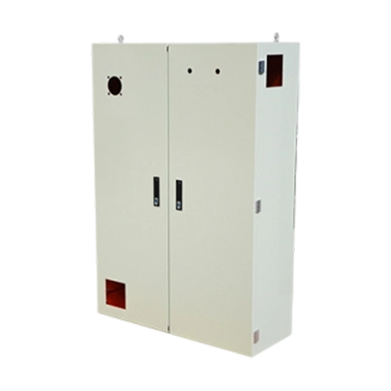
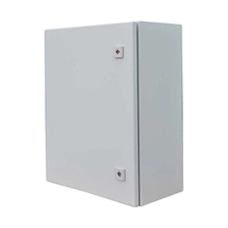
Control cabinets combine a structural frame with removable panels. The equipment must produce repeatable hole patterns for mounting rails, cable glands, and door hardware. CNC punching with a multi tool turret reduces setup time and ensures that the tenth cabinet matches the first.
Precision stamped components
Small stamped parts may be produced on high speed presses rather than turret punches. The equipment choice depends on annual volume, material thickness, and the number of forming operations. Progressive die tooling can combine cutting, forming, and separation in a single pass.
Quality Control Measures That Support Equipment Claims
Equipment specifications are only credible when backed by measurement. A supplier that claims plus or minus 0.1 mm position accuracy should be able to show inspection data that proves it.
First article inspection: measures all critical dimensions on the first part of a production run and compares them to the drawing.
In process inspection: checks key dimensions at defined intervals during production to detect drift before it becomes a batch problem.
Final inspection: verifies the completed part, including bend angles, hole positions, surface finish, and assembly fit.
Material verification: confirms that the incoming sheet matches the specified grade and thickness before processing.
Equipment calibration: maintains laser power, press brake angle measurement, and CMM accuracy on a scheduled basis.
For custom control cabinets and equipment housings, the inspection plan should include the assembly interface. A panel that meets its individual drawing but does not fit the frame is still a nonconforming part.
Commercial Factors in Mechanical Production Equipment Selection
Technical capability and commercial reality must align. A supplier may have the right equipment but not the capacity, lead time, or cost structure for a particular project.
Factor
What to verify
Impact on project
Lead time
Tooling, sampling, and production schedule
Determines project timeline and inventory planning
Minimum order quantity
Setup cost amortisation
Affects unit price for custom enclosures
Tooling ownership
Who owns dedicated tooling
Affects future sourcing flexibility
Inspection documentation
Reports, certificates, and traceability
Required for regulated industries
After sales support
Spare parts, technical response, and field service
Reduces downtime and production risk
These factors should be discussed before the first sample is produced. Changing them later is expensive for both the buyer and the supplier.
Frequently Asked Questions
Q1: What materials can your mechanical production equipment process?
Our equipment processes mild steel, stainless steel, aluminium, copper, brass, and pre coated sheet. The practical thickness range depends on the process. Laser cutting covers 0.5 to 20 mm mild steel and 0.5 to 12 mm stainless steel. CNC punching is typically used from 0.5 to 6 mm. Press brake forming covers 0.5 to 12 mm depending on bend length and tooling.
Q2: How long does custom manufacturing take from order to delivery?
Lead time depends on tooling requirements, sample approval, and production volume. A typical custom enclosure project takes two to three weeks for sampling and four to six weeks for production after sample approval. Projects requiring dedicated tooling may add one to two weeks for tool design and manufacture.
Q3: How do you guarantee bending accuracy on large cabinets?
Bending accuracy is controlled through a combination of machine calibration, tooling condition, and angle measurement. For large cabinets, we use press brakes with deflection compensation and verify the first part against the drawing. In process inspection checks bend angles at defined intervals. Material springback is accounted for in the bend allowance calculation before production begins.
Q4: Do you provide overseas installation and after sales support?
Yes. For custom production equipment and fabricated assemblies, we provide documentation, inspection reports, and technical support. Field installation and commissioning can be arranged for larger projects. Spare parts and replacement components are available through our standard support process.
Q5: What information do you need to quote a custom project?
To provide an accurate quote, we need the 3D model or 2D drawing, material specification, surface finish requirement, quantity, and any assembly interfaces. If a sample is available, that also helps. Early involvement allows us to raise design for manufacturability issues before tooling is committed.
Need a Custom Mechanical Production Solution?
Send your drawing, material specification, and quantity. We will review the process route, identify any manufacturability risks, and return a quote within 24 hours.
Get a quote in 24 hours. Contact our engineering team with your project details and we will respond with a process recommendation and commercial proposal.


 English
 русский
 Español
 中文简体
中文简体